Progressive cavity pumps, also known as PC pumps and single screw pumps, are positive displacement pumps. With a wide range of industrial applications, it can transport almost any substance continuously, at a constant pressure, gently and with low pulsation. Whether it is wastewater sludge, chemicals, slurries, adhesives, oil or shear-thinning non-Newtonian fluids.
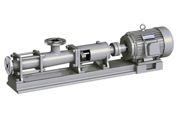
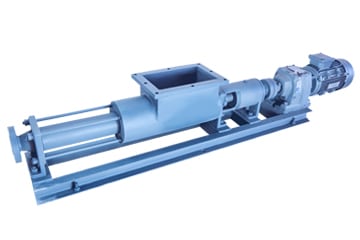
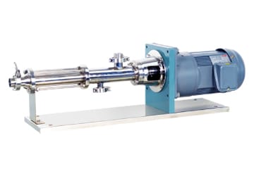
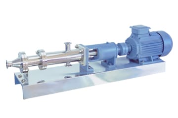
AOBL is a professional manufacturer of progressive cavity pumps and offers a wide range of PC pumps including conventional, open hopper type, dosing type and stainless steel food grade. With a wide range of rotor/stator geometries and a variety of engineered fittings in the right combination to meet your application requirements, AOBL progressive cavity pumps are cost-effective and low-maintenance, and are available in a wide range of sizes and materials, with flow rates from 0.3 m³/h up to 150 m³/h.
Design and working principle of progressive cavity pumps
The design of progressive cavity screw pump is simple and compact. It mainly consists of pump casing, screw, bearings, seals and transmission device. The pump casing is usually made of cast iron or stainless steel with good sealing. The screw is in the shape of a single helix and forms a sealing working chamber by cooperating with the inner surface of the pump casing. The screw is usually made of stainless steel or hard alloy with high wear and corrosion resistance. Bearings are used to support and position the screw to ensure its proper operation. The selection of seals is very important to ensure the sealing performance and working efficiency of the pump. The drive can be a motor, gearbox or other transmission device for driving the rotation of the screw.
The operating principle of a progressive cavity pump is based on a cam motion between the screw and the pump casing. Inside the pump casing there is a spiral groove, while the screw is responsible for rotating and moving inside the spiral groove. As the screw rotates, the liquid is drawn into the spiral groove and gradually pushed forward as the screw rotates. During this process, the liquid is restricted by the spiral groove and pushed by the cam, forming a sealed working chamber. As the screw continues to rotate, this sealed working chamber will gradually move forward along the helix, discharging the liquid from the inlet to the outlet.
progressive cavity pump usage
Single screw pump outlet rated pressure can be increased with the increase in the number of pump stages, each additional level, the pressure increased by 0.6MPa, so the application range is very wide.
- Environmental protection: industrial sewage, domestic sewage, sludge containing solid particles and short fibers turbid water transport. Especially suitable for plate and frame filter press and other equipment.
- Shipbuilding industry: wheel bottom cleaning, oil and water, oil sludge, oil sewage and other media transportation.
- Petroleum industry: conveying crude oil, the use of screw pumps to the formation of polymer injection to increase the recovery rate of oil fields.
- Pharmaceuticals, daily chemical: a variety of viscous slurry, emulsion, various ointments and cosmetics, such as transport.
- Food canning industry: all kinds of viscous starch, cooking oil, honey, syrup, fruit syrup, cream, minced fish and minced meat and its scraps of transportation.
- Brewing industry: a variety of fermentation viscous liquid, thick wine lees, grain product residue, various sauces, pulp and viscous liquid containing lumpy solids transportation.
- Construction industry: cement mortar, lime slurry, paint and other paste spraying and transportation.
- Mining industry: sewage and slurry water containing solid particles in the mine are discharged to the ground.
- Chemical industry: transportation of various suspensions, grease, colloidal slurry and adhesives.
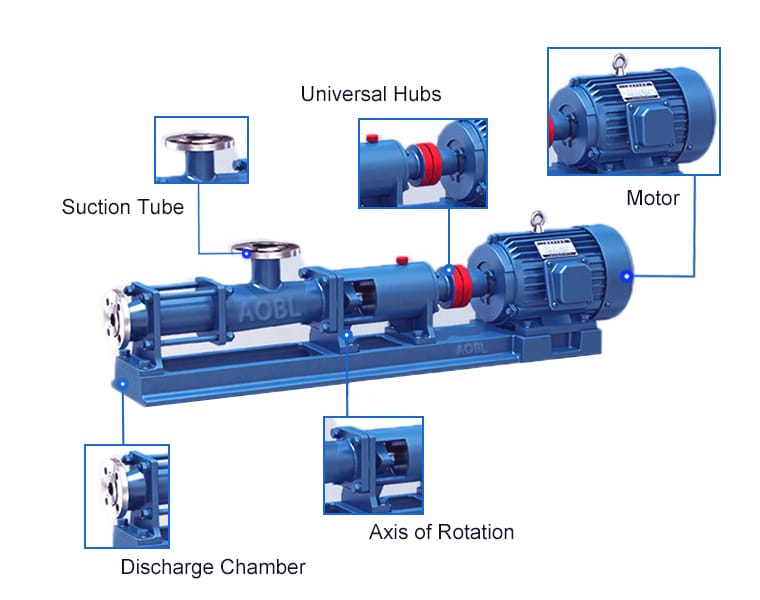
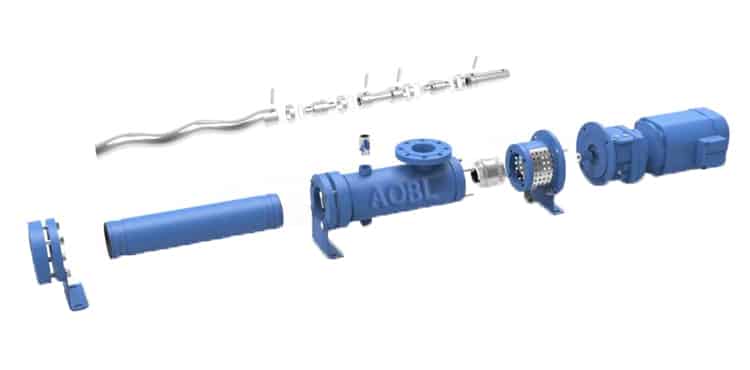
progressive cavity pump parts
The main parts of progressive cavity pump include discharge chamber, rotor, stator, universal joint, intermediate shaft, suction chamber, shaft seal, bearing housing assembly, etc.
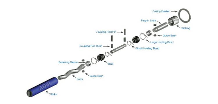
- Rotor: according to the media characteristics, there are a variety of materials to choose from (304, 316L)
- Stator: the stator rubber sleeve material can be selected from a variety of rubber materials such as nitrile rubber, fluorine rubber, EPDM rubber, super abrasion-resistant rubber, food-grade rubber, etc., which is able to meet a variety of abrasive, corrosive, high-temperature and other harsh working conditions.
- Universal joints: rubber sheath on the outside, grease lubrication on the inside, national standard cross shaft structure, high transmission torque, high reliability, long life, easy maintenance.
- Shaft seal: packing seal, single-end mechanical seal, double-end mechanical seal and other sealing methods, and packing seal and single-end mechanical seal can be interchanged.
- Inlet chamber and outlet short connection: there are various materials for choice, and the inlet chamber can realize the direction of upward, leftward and rightward interchangeable, the installation mode is more flexible.
- Bearing housing or support frame: when the reducer and pump are connected by coupling, the bearing housing structure is adopted; when the reducer and pump are directly connected, the support frame structure is used.
progressive cavity pump advantages and disadvantages
advantages
- Continuous and low pulsation conveying, not affected by pressure and viscosity fluctuation.
- Wide range of applications, can transport flowing or even non-flowing materials.
- The medium in the pumping process will not be stirred, free from extrusion and shear.
- High efficiency, the conveying capacity is proportional to the rotating speed, and the conveying capacity can be adjusted by frequency conversion.
- Most of the liquids can be pumped under small agitation and pulsation.
- Easy maintenance and repair, with high pressure conveying capacity.
disadvantages
- The processing and assembly requirements of the screw are high, and the performance of the pump is sensitive to changes in the viscosity of the liquid.
- Stators made of rubber and other materials have a short service life, and vibration will be louder than other pump vibration sounds.